ELAB WEEK 1
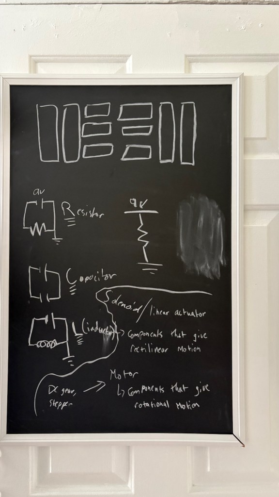
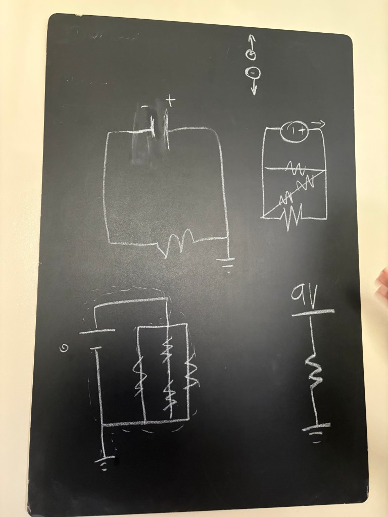
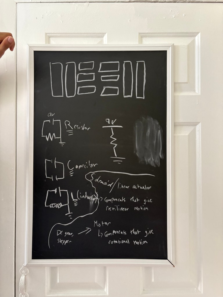
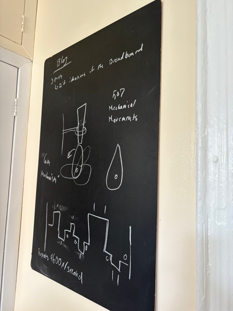
As I entered weeks four and five of the ITP program and Physical Computing, I realized I needed to truly understand what I was looking at—not just follow instructions, but grasp the underlying logic. I decided to step back and revisit the fundamentals. With the help of Nava, a fellow first-year student, I began to unpack the core building blocks of electronics: ground, circuits, rails, components, and power supply. They walked me through how each of these elements interacts within a system, helping me see the invisible flow of electricity not just as a technical process, but as a structured language that everything in Physical Computing speaks.
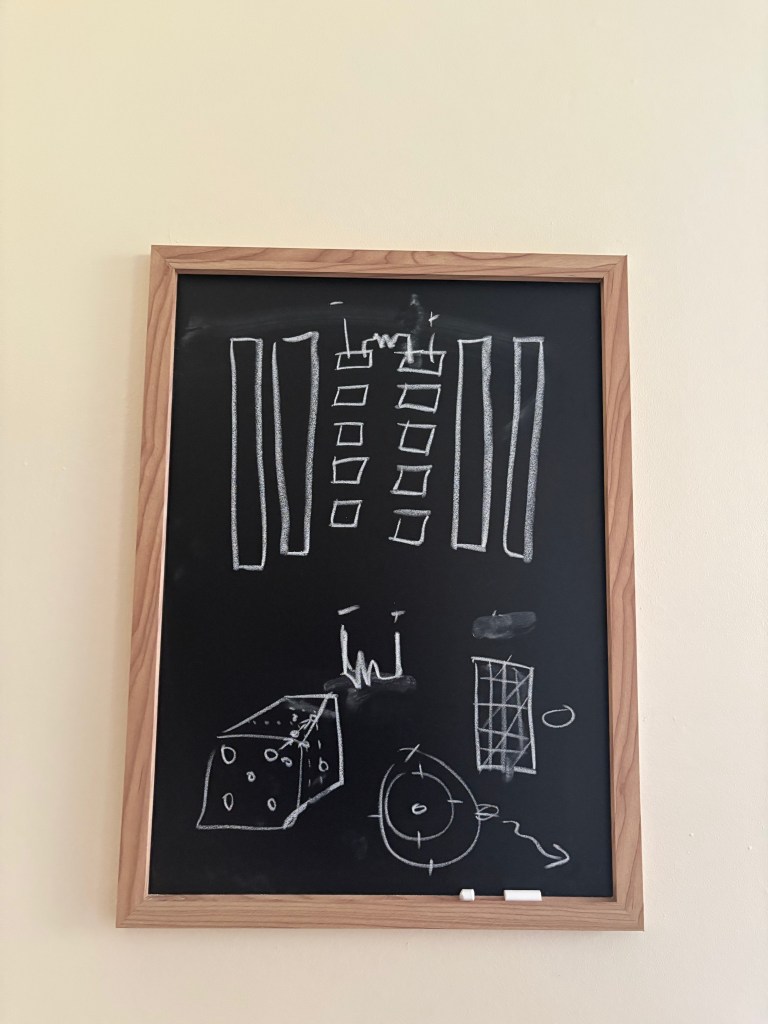
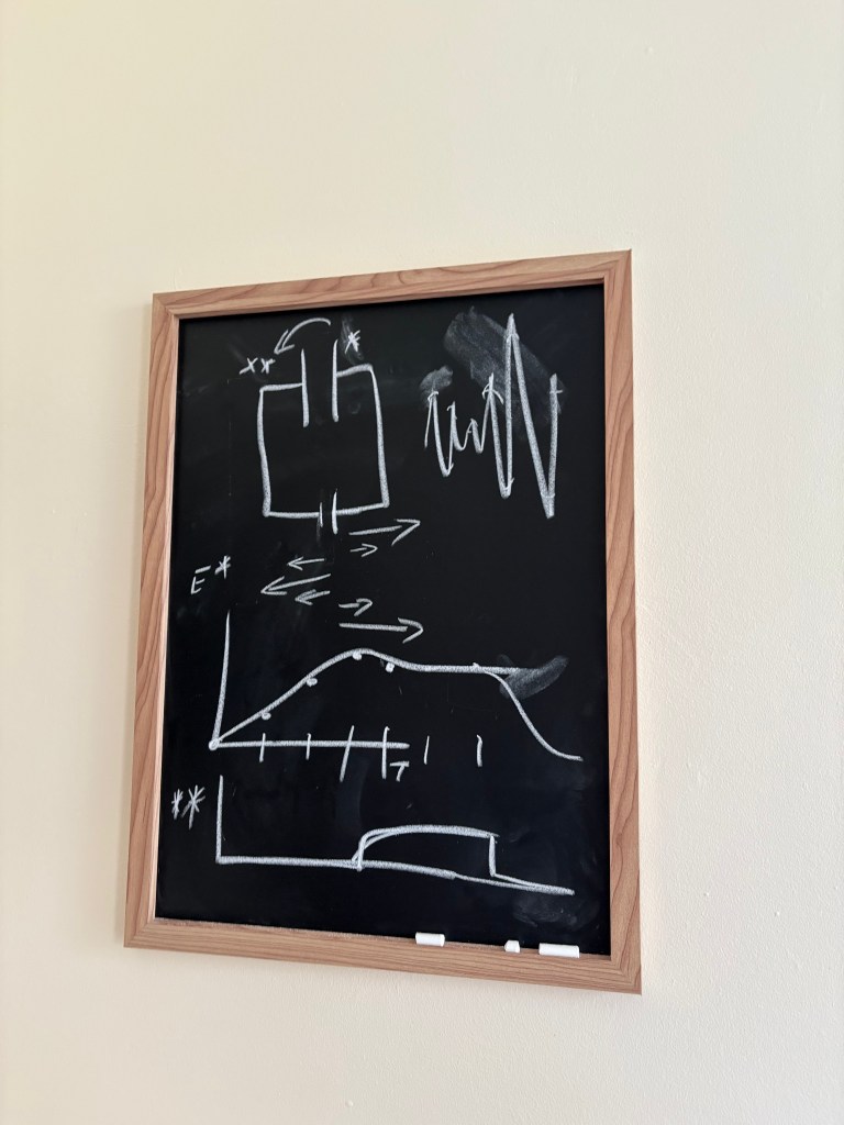
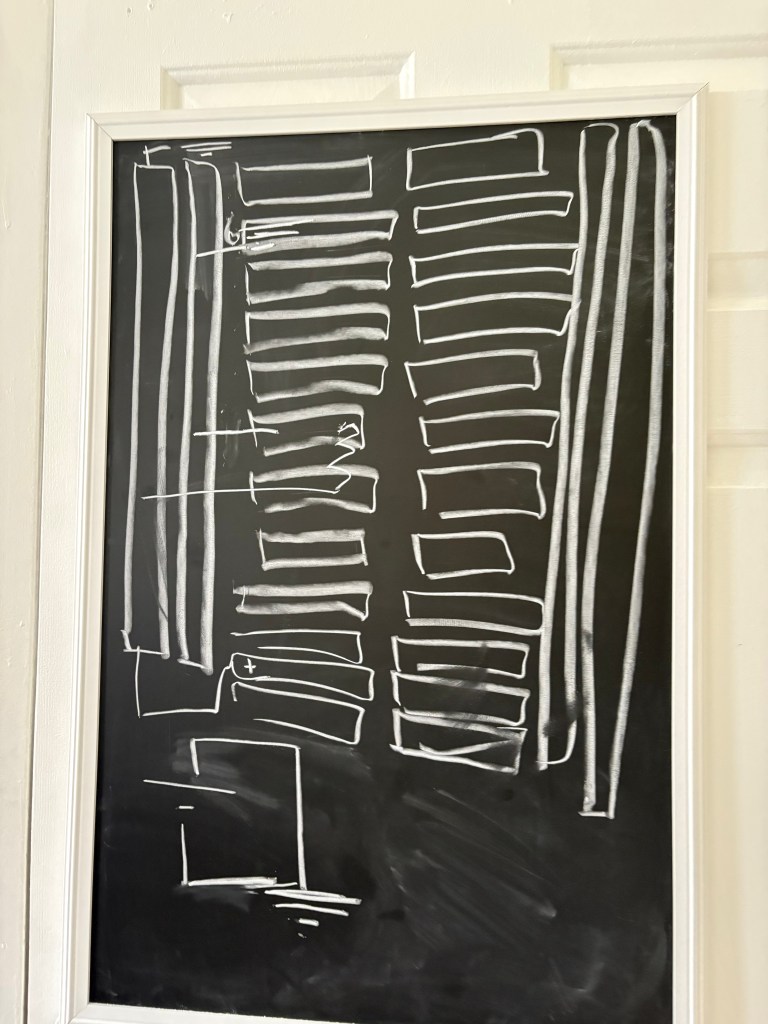
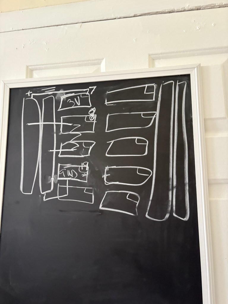
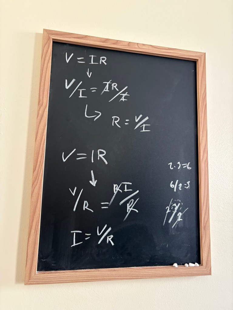
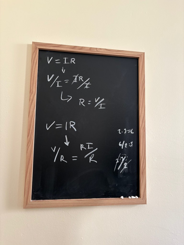
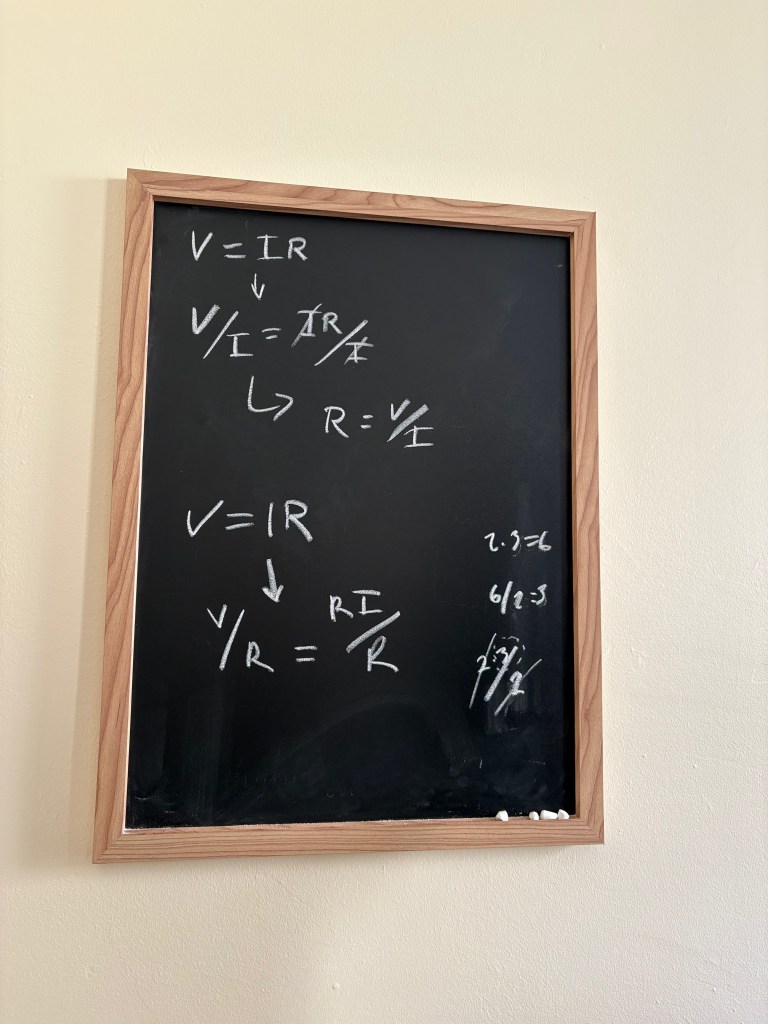
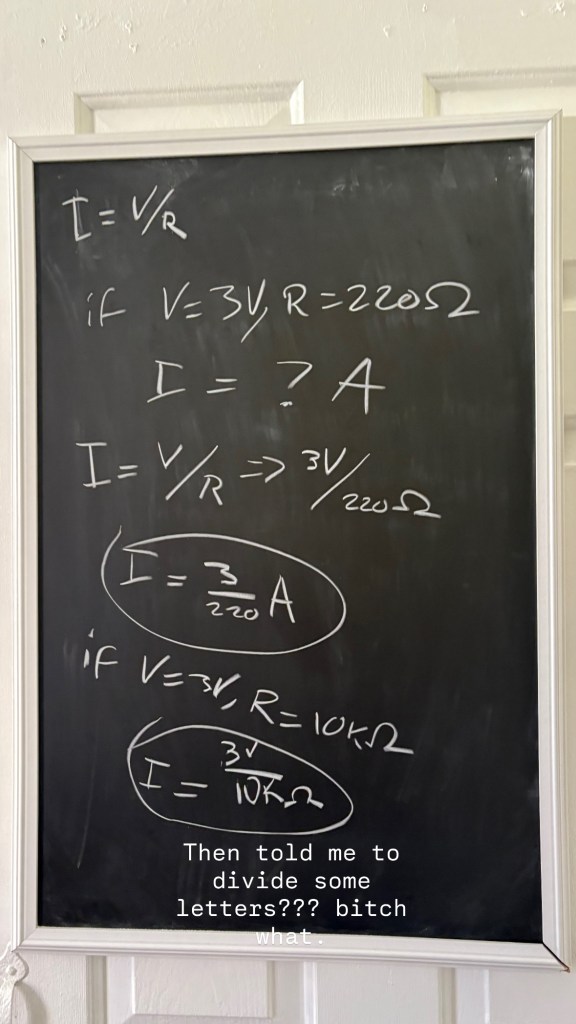
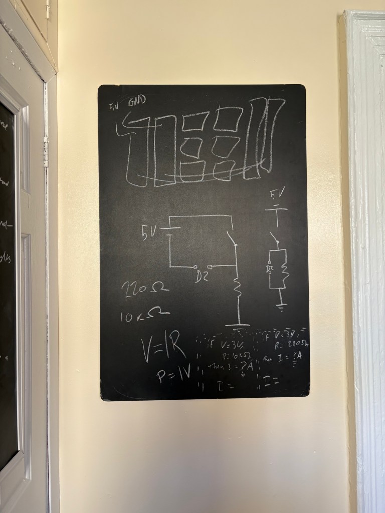
The first study session below you will see Nava coaching me through the diagrams of the breadboard

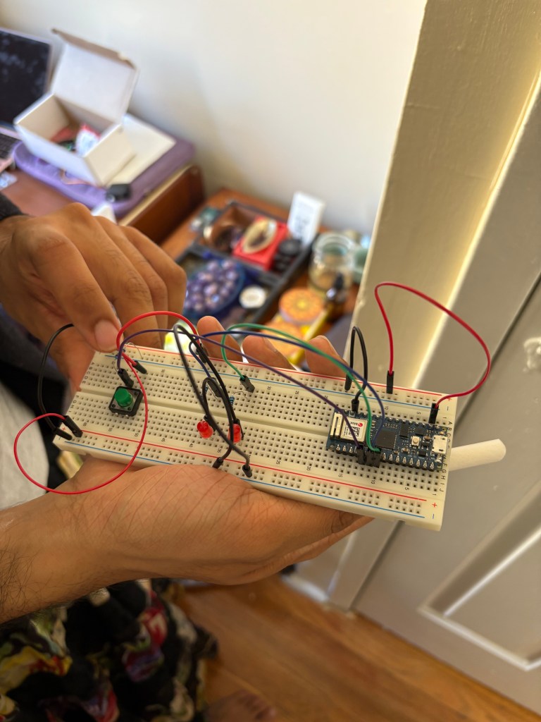
Result:
My first attempt at creating an LED light circuit, completed with the guidance of Nava.
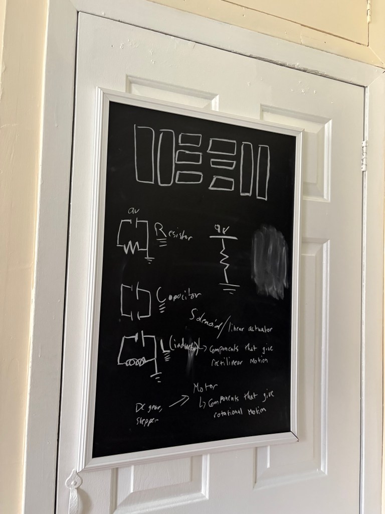
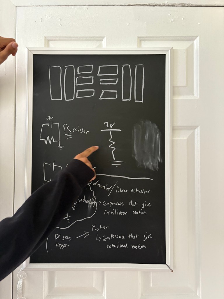
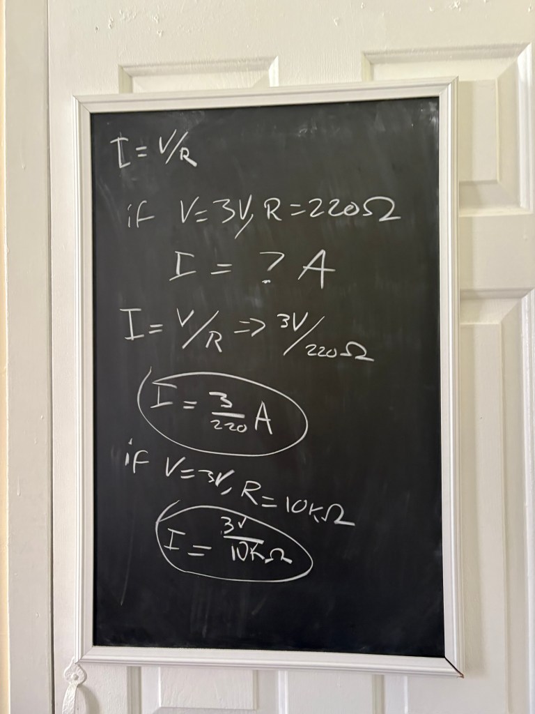
I specifically used this diagram to help me with the circuit
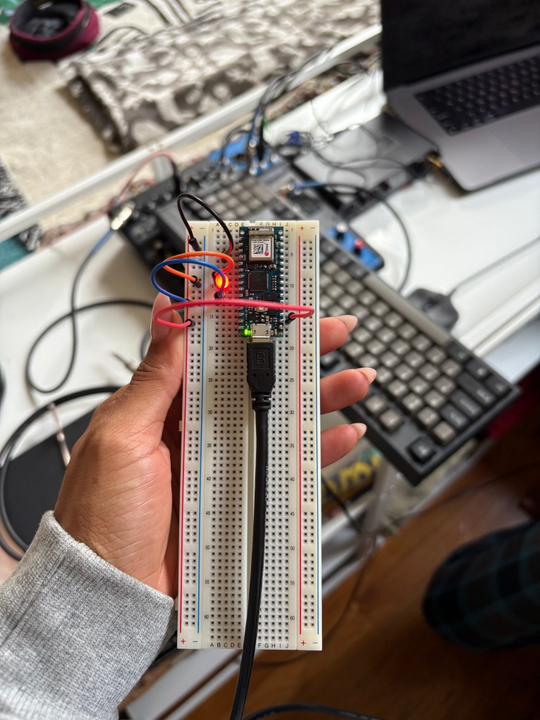
This is my second attempt. While the first one looks cleaner because of the chords, the circuit was not successful
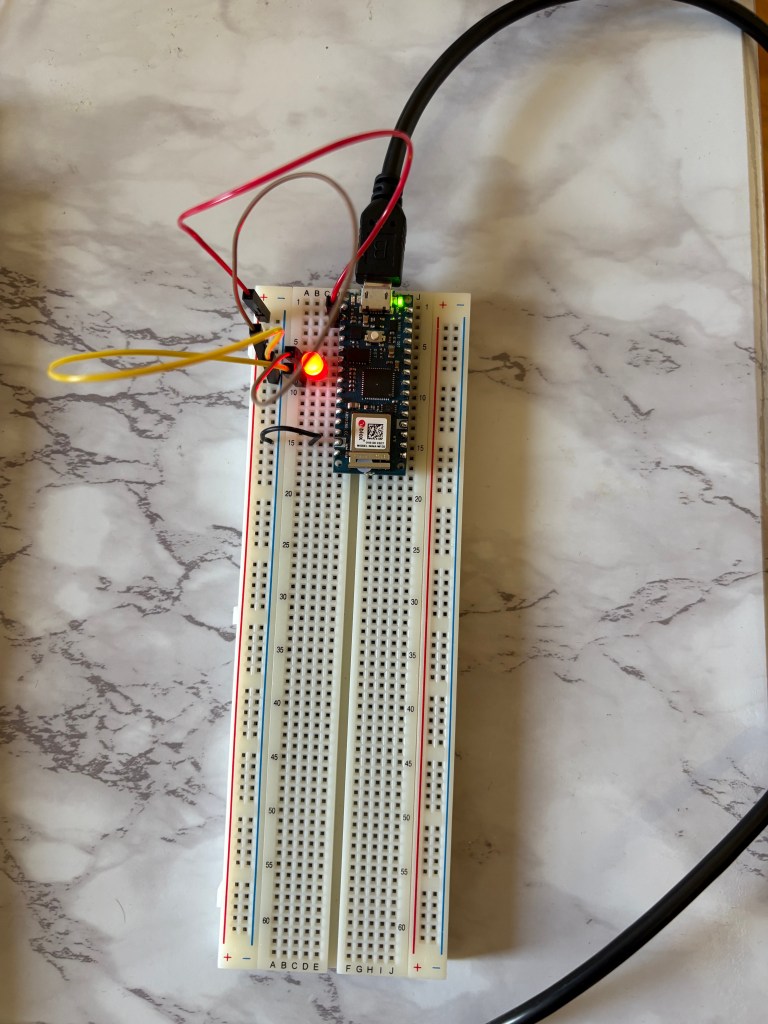
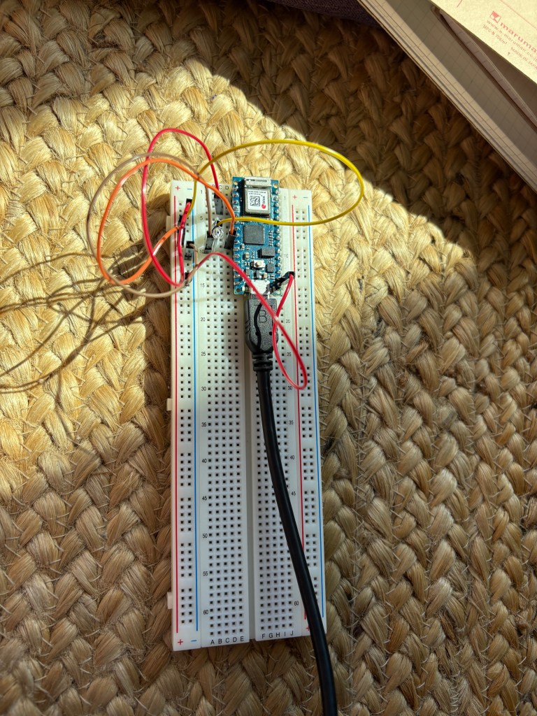
This was my third attempt at the circuit, which was successful, and I felt like I was ready for Lab 2.
ELAB WEEK 2
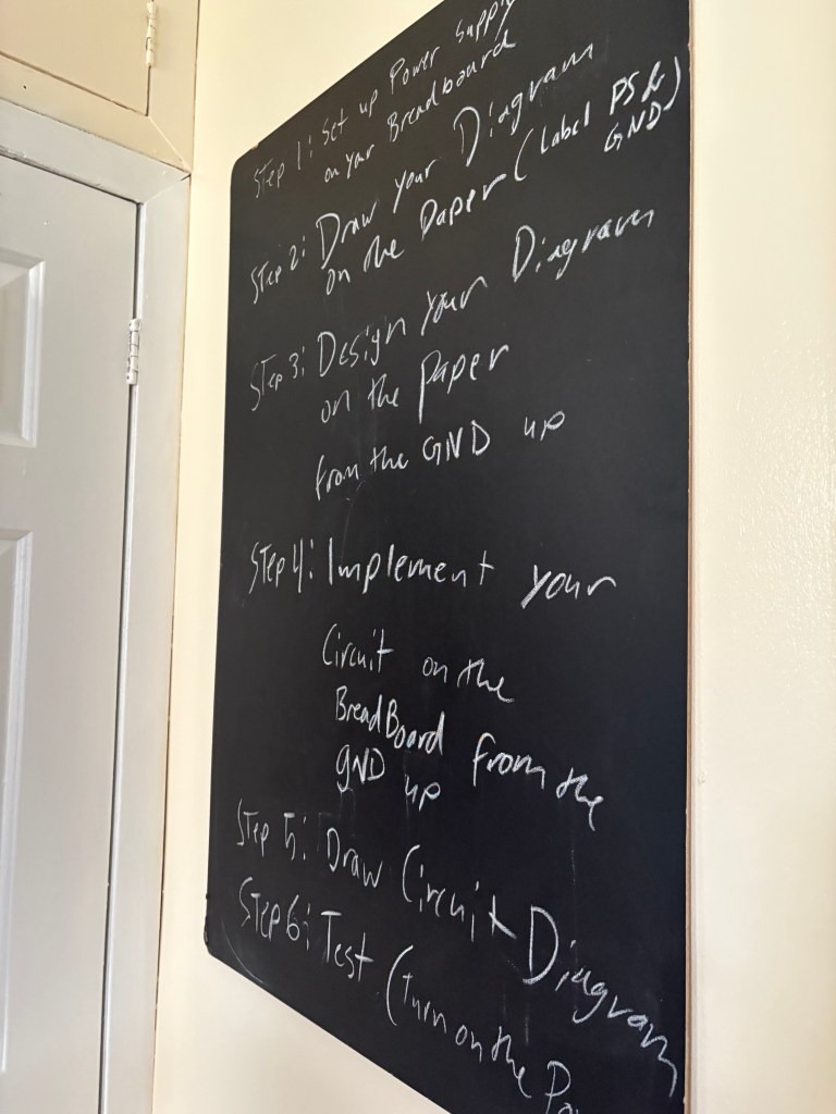
With Week 2 lab, I wanted to get a better grasp on how to actually read and move through the labs efficiently. This lab focused on Digital Input and Output and Analog Input, and once I understood the structure of the labs, everything started to click. I was able to move through the exercises quickly and began setting up my Arduino to test things out in real time.
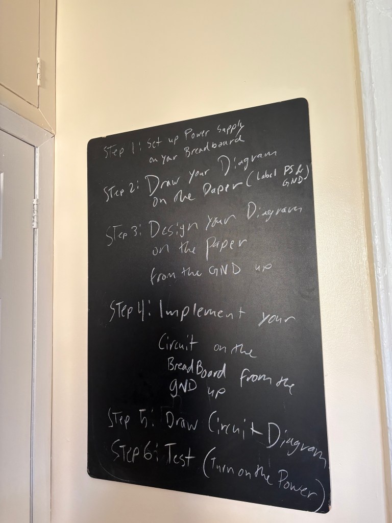
Here are a few photos from my study session with Nava. I learned that with Elabs, it is better for me to right out the diagrams, and follow those, and then build the breadboard.
Here is where I set up the second Elab successfully and now it was ready to program to Arduino.
After being programmed in Arduino
The 3.3V pin outputs a steady voltage signal, which runs from my powered rail to rail #53, where it hits my button. Unpressed, the button introduces a break in the circuit; when I press the button, it connects my power lead to rail #55 where I have a resistor leading to ground in parallel with a cable connected to my D2 Read Pin. Pressing the button completes the circuit and sends a voltage signal to my D2 Read pin, which my Arduino detects. When the Arduino detects a voltage signal through D2, it outputs a voltage through D3; when the button is not pressed, the Arduino outputs a voltage through D4.
My Voltage signal runs from my power rail to Rail 36, and Rail 40 is Grounded. My A0 pin is connected to Rail 38, and a potentiometer is plugged in to Rails 36, 38, and 40. On the other side of my breadboard, I have an LED in series with a resistor. Voltage will run from my D9 pin into Rail 45. The charge will move through my 220 Ohm resistor from Rail 45 to Rail 51, into the anode of my LED, and out the cathode into Rail 53, and into ground from there. The setup code from the Arduino is initializing serial communications at Baud rate of 9600 bps and declaring the LED pin as a Write pin. The loop of the Arduino REPL is reading through the potentiometer for a variable voltage signal, and controlling the voltage amount supplied to the LED in response to that monitored value; it is printing this brightness value to the console.
ELAB WEEK 3
By Week 3 of eLab, I could follow a lab with ease, so we moved on to tone input and output. What stood out in this exercise was the hands-on precision it required—specifically getting the breadboard and speaker to function properly. It came down to careful placement: ensuring the leads were positioned close together along the rails and being meticulous about every component’s alignment to make the circuit work.

(The music playing is studying music, the humming is the actual speaker)
For this tutorial, I built a circuit that uses an analog sensor to control the position of a servomotor through a microcontroller. The video below shows the completed project. By Lab 3, I no longer needed to rely on drawing circuit diagrams as much and decided to reserve that process for my midterm project instead.
ELAB WEEK 4
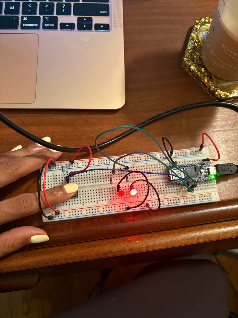
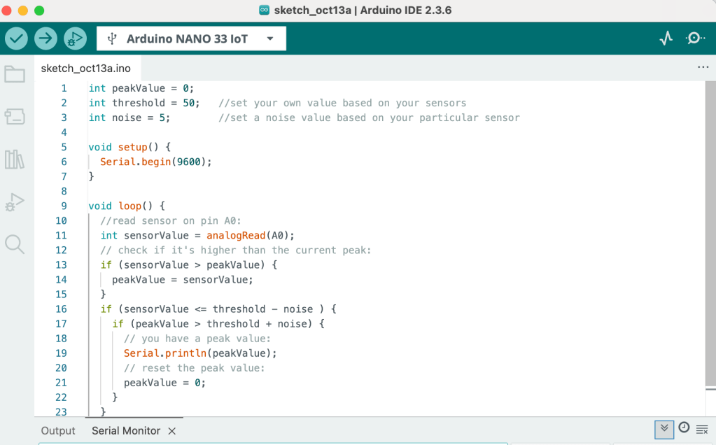
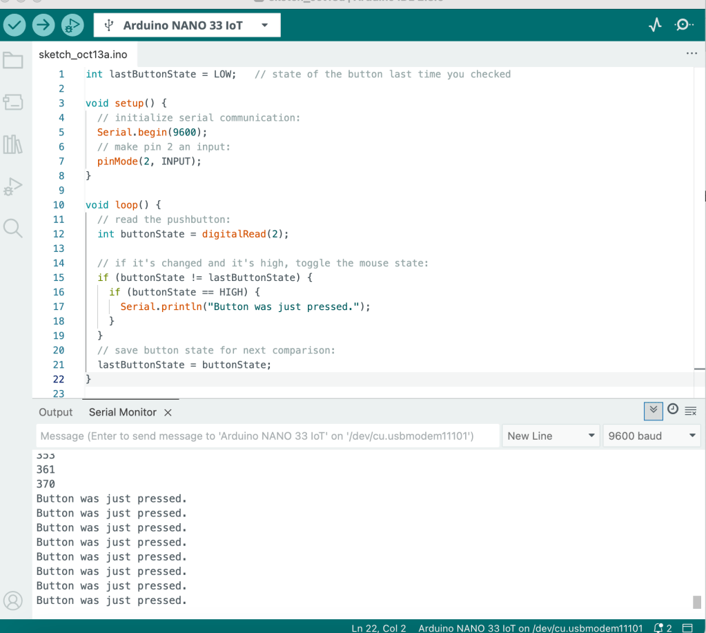
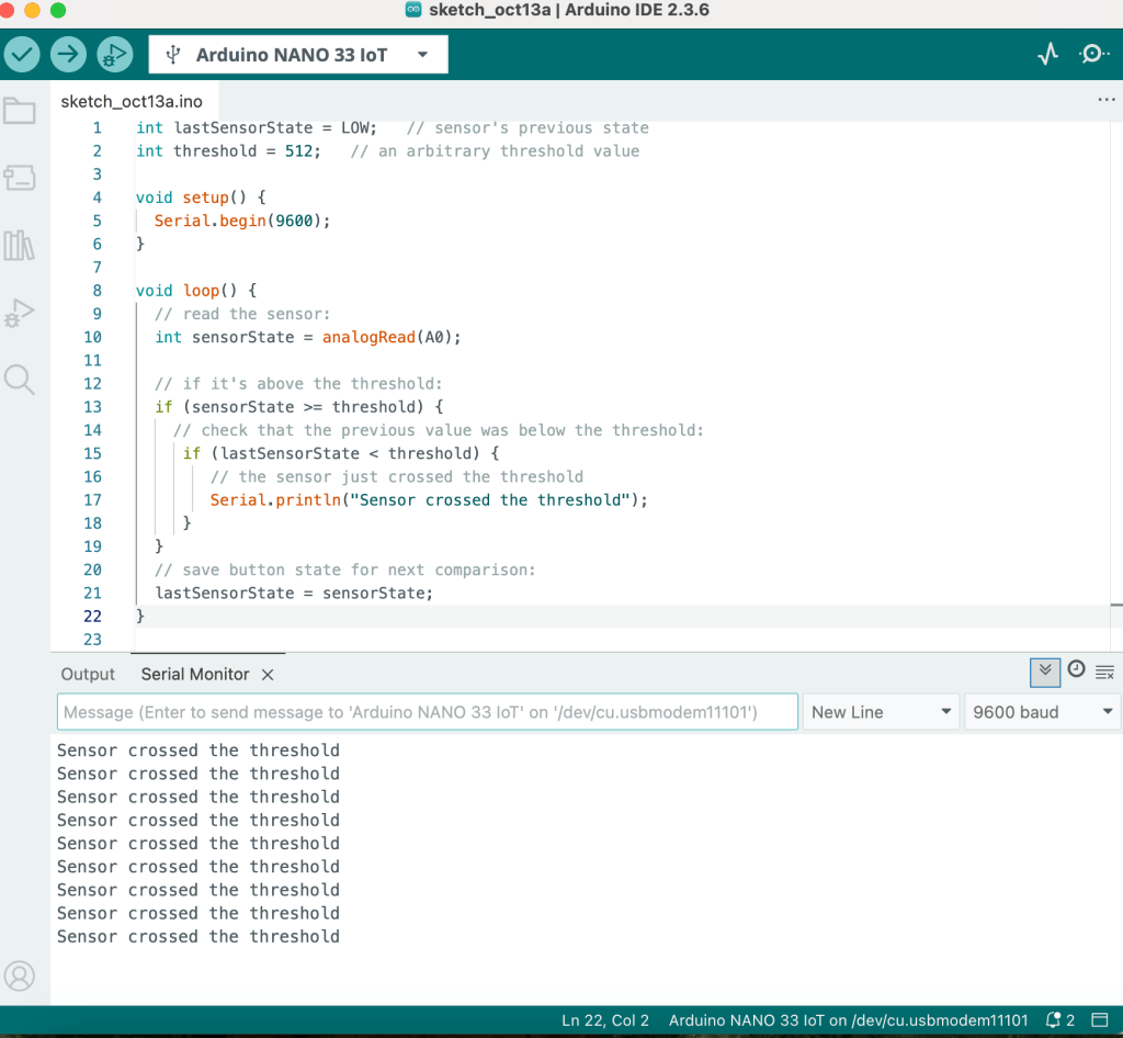
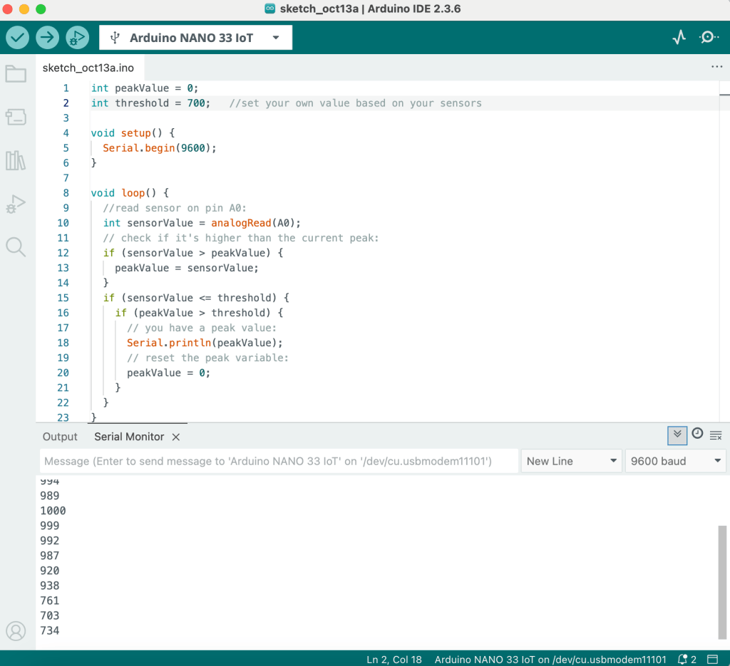
For Week 4, I was experimenting with how microcontrollers respond to changes in sensor data. I played around with both digital and analog inputs to understand how state changes, threshold crossings, and peak detections work in real time. This helped me see how code and hardware communicate — how even small shifts in sensor readings can trigger meaningful reactions in a circuit.
ELAB WEEK 5
